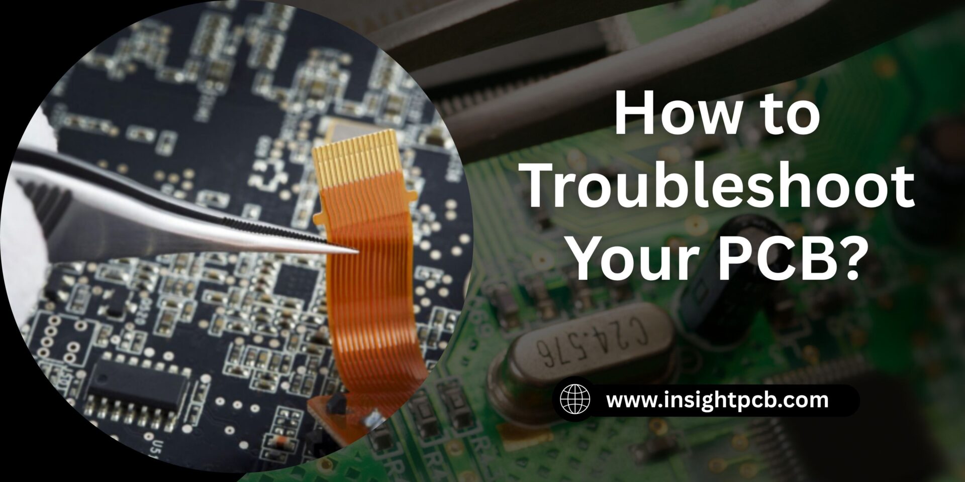
How to Troubleshoot Your PCB?
A Printed Circuit Board (PCB) is one of the most significant inventions in electronics. It combined several circuits and chips into a single small board. They are used in everything from smartphones to computers. They are considered to be the backbone of a device. So, naturally, if it stops working or malfunctions, the whole device falls apart. That is why it is necessary to understand the basics of PCBs and how to troubleshoot them.
In this blog, we will discuss how to troubleshoot PCBs and various methods to do so. This would help extend the life of your device.
What causes PCB damage?
First, we need to understand what causes damage to them to better understand PCB troubleshooting. Here are some reasons your PCB may become damaged:
-
Component malfunction/breakdown
One of the most common reasons for defective PCBs is that a component malfunctioned or had a breakdown. This can be due to faulty components or some integral issue. Replacing them usually fixes the problem.
-
Overheating
If there is no proper heat management system, there is a good chance that the circuit may get damaged from the residual heat itself. In such cases, either of the components of a PCB may fail.
-
Physical damage
The mishandling of the components is often the cause. The stress can damage the soldering, capacitors, or even break the board itself.
-
Contamination
If your board is exposed to harsh conditions, the copper may become damaged or corrode.
How to troubleshoot a PCB?
You will find that troubleshooting a PCB isn’t that difficult a task. In fact, with the right tools and knowledge, you can do it yourself. Here’s a guide on how to troubleshoot PCB:
Gather the Required Tools
The right tools will help you immensely. They will enable you to identify and repair the problematic areas on the board easily. These tools include a multimeter, probes, an oscilloscope, an LCR meter, and an external power supply. The latter are only required if you’re handling bigger boards. For simpler ones, a multimeter and two probes are more than enough.
Map Out the Circuit
All circuit boards have a schematic diagram. These are helpful as they help understand how the components are connected. There can be components like voltage dividers, capacitors, filters, etc. If you know how the circuit is connected and mapped out, it becomes easier to know where to start. You can then compare the circuit paths to those of the schematic diagrams and isolate the defective part. After that, it just becomes a matter of replacing it.
Visual Inspection
Usually, it’s very easy to isolate the defective part if the underlying cause was overheating. Other indicators for PCB troubleshooting include parts that are:
- Bulging or overlapping
- Dulled out copper traces
- Weak solder joints
- Lifted or missing
- Cracks on the board
If you’re experienced in the process, you may be able to repair the board just by looking at it and finding the defective part.
Compare with an Identical Circuit Board
If you can, then obtain a similar circuit or a photo of it. Then you can compare them side by side. If there is any physical damage or missing parts, you’d easily be able to figure them out by a simple comparison.
Isolate Defective Components
If you’re unable to find the defective part using previous methods, you can use a multimeter and probes for assistance. Compare the current output of each component with the requirement datasheet. You will find that the defective components either pass no current or less than the assigned rating. After isolating the part, use a solder to remove it and then replace it.
There can also be problems with the soldering joints, so always compare the output voltage with the assigned one. If that is the case, then only fresh soldering will be able to repair the circuit. After that, you can easily perform PCB board troubleshooting.
Check the Power Supply
Always check the power supply first; it should be set at the input rating of the board. Moreover, if there are any other components that are damaged, they would be outputting a different voltage than the assigned one.
The Circuit’s Hot Spot
If all previous methods fail, there is yet another, and an easy one. Damaged components are known to emit heat in quantities larger than any other. This creates a hotspot around it. This can either be felt by placing your finger on the circuit, but the safer option is to use a thermal camera. Using the camera, you would easily locate the circuit’s hotspot and mend it.
Important Safety Guidelines for PCB Board Troubleshooting
The process may seem simple, but if defective components are involved, you may get shocked or burned. Here are a few tips to ensure your safety:
- Always wear protective gear when PCB troubleshooting. This can include gloves, the use of electrical tape, or simply being attentive while working.
- To prevent electric discharge, always unplug the circuit. You should also fully discharge the device.
- Components like capacitors are known to retain their charge even after the power supply is disconnected, so ensure they are discharged before working.
Conclusion
As important as PCBs are, it’s equally important to repair them when they stop functioning. To fix them, you first need to understand how to troubleshoot PCB boards. You can easily work on the board, as the guide for simpler PCBs is very easy. It’s just a matter of isolating the defective component using a series of inspections. Once you have, replace the faulty part, and it’s good to go.
Ready to extend the life of your devices? Trust Insight PCB for expert solutions, reliable repairs, and top-notch PCB services.